
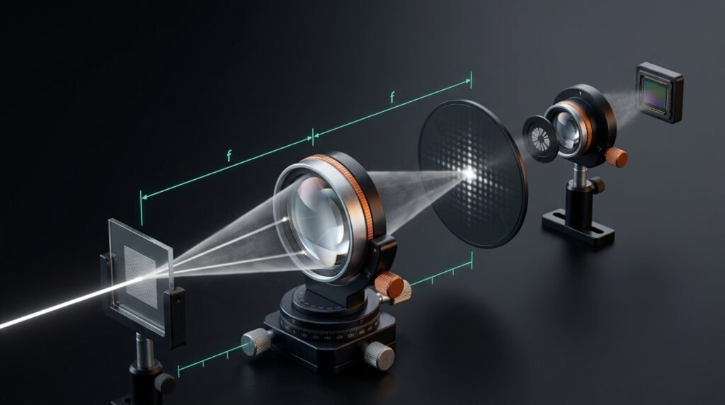
TL;DR
A Fourier transform lens is a positive lens used so that the light pattern at its back focal plane is the Fourier transform of the pattern at its front focal plane. In plain terms, it turns the direction of light into position. This guide explains the principle, the f-to-f and 4f layouts, real applications, and a five-point checklist for choosing one.
Quick Answer
A Fourier transform lens is a lens placed so that the input sits one focal length in front of it and the result is read one focal length behind it. In that arrangement, the lens converts each angle of incoming coherent light into a position on the focal plane. The pattern that appears is the spatial frequency spectrum of the input. This is the basis of optical filtering, correlation, beam shaping and far-field measurement.
Introduction
Most people meet a lens as an image maker. Put an object on one side, and a sharp picture forms on the other.
A lens does something else at the same time, and it is far less obvious. Look at the plane exactly one focal length behind it, and you will not find a picture. You will find the object’s spatial frequencies laid out as a pattern. Fine detail lands far from the axis, while broad features gather near the centre.
That second job is what a Fourier transform lens is for. It is the quiet workhorse behind spatial filtering, optical pattern recognition, beam shaping and many laboratory measurements.
This article explains what a Fourier transform lens is, why the physics works, and how the f-to-f and 4f layouts are built. You will also find worked numbers, common applications, a selection checklist, alignment tips and the mistakes that trip up newcomers.
What Is a Fourier Transform Lens?
A Fourier transform lens is a positive lens used in a way that makes it perform an optical Fourier transform. When coherent light carrying a pattern passes through it, the intensity at the back focal plane matches the Fourier transform of that pattern.
The phrase describes a use as much as a product. A simple singlet can act as a Fourier transform lens in a classroom demonstration. In precision work, designers choose multi-element lenses tuned for the job, with tight control of distortion and wavefront error.
The Fourier plane in plain language
The plane where the transform appears is called the Fourier plane, or the transform plane. Each point in that plane corresponds to one spatial frequency in the input.
Picture a fine window screen next to a coarse garden net. Light passing the fine screen spreads to wide angles, so it lands far from the axis. Light passing the coarse net spreads to narrow angles, so it lands close to the axis. The lens reads those angles and writes them down as positions.
Why the name says “Fourier”
Joseph Fourier showed that complicated signals can be built from simple waves. A pattern in space can be treated the same way, as a sum of sinusoidal gratings with different spacings and directions. The transform tells you how much of each grating is present.
A Fourier transform lens produces that breakdown with light itself. No computer is needed, and the result appears across the whole plane at once.
How a Fourier Transform Lens Works
The angle-to-position translator
A useful mental model is to treat a Fourier transform lens as an angle-to-position translator. A plane wave that enters at a given angle is focused to a single point on the back focal plane. A wave at a different angle goes to a different point.
A coherent input pattern can be viewed as many plane waves travelling at slightly different angles. The lens sorts all of them at once. Where each wave lands depends only on its angle, not on where it crossed the lens.
That is the heart of the principle. Position in the input is traded for angle, and angle is traded for position in the output.
The key relationship
In the standard small-angle theory, the position in the Fourier plane is u = λ × f × fx. Here λ is the wavelength, f is the focal length, and fx is the spatial frequency of the input in cycles per unit length.
Three practical points follow from this. A longer focal length spreads the pattern wider. A longer wavelength does the same. And finer detail in the input, which means a higher spatial frequency, lands farther from the axis.
A worked example
Suppose a grating with 10 lines per millimetre is lit by a collimated 633 nm beam. A Fourier transform lens with a 200 mm focal length sits behind it. The spatial frequency is 10 cycles per millimetre.
Multiply 0.000633 mm by 200 mm by 10 per millimetre, and the first diffraction order lands about 1.27 mm from the axis. Swap in a 400 mm lens, and the same order lands about 2.5 mm away. The pattern simply scales with focal length.
This is why the focal length you choose acts like a magnifier for the transform plane.
Why coherent light matters
The clean relationship holds for coherent illumination, such as a laser. With ordinary incoherent light, contributions add as intensities rather than as complex amplitudes, and the neat transform relationship does not appear in the same way.
For that reason, a Fourier transform lens is usually paired with a laser or a well-collimated, filtered source.
The f-to-f Layout and the Focal-Plane Handshake
The cleanest arrangement for a Fourier transform lens is the f-to-f layout. The input sits one focal length in front of the lens, and the output plane sits one focal length behind it. The total path from input to output is 2f.
A simple way to remember this is the focal-plane handshake. The input plane and the Fourier plane each meet the lens at exactly one focal length. When both distances equal f, the transform is exact in the standard small-angle theory, including its phase.
Distance errors have different effects depending on what you measure. If the input sits slightly closer to or farther from the lens, the intensity pattern in the focal plane is still essentially the transform magnitude. A curved phase factor appears, though, and that matters when the phase is used. Holography and matched filtering are the usual examples.
If the input is placed behind the lens instead, the scale of the pattern changes with the distance to the Fourier plane. That can be handy, but it needs to be calculated, not guessed.
A plain collimated beam with no pattern is a special case. It is a single spatial frequency, so the lens focuses it to a bright spot on the axis. That is exactly what a focusing lens does, which shows how closely the two roles are linked.
The 4f System: Two Lenses, Two Transforms
Add a second lens, and you get the 4f system. The first lens sits one focal length after the input. The Fourier plane forms one focal length behind it. The second lens sits one focal length beyond that plane, and the output appears one focal length behind the second lens.
With two lenses of equal focal length, the total length is 4f. The first Fourier transform lens performs a forward transform, and the second performs a transform that brings the light back into an image. The result is a copy of the input, flipped in both directions.
The point of the layout is the middle. The Fourier plane is physically accessible, so you can place a mask there and change the image in useful ways.
A small circular aperture blocks high frequencies, which smooths the image. A central stop blocks low frequencies, which sharpens edges. A narrow slit passes only features with a certain orientation.
If the two lenses have different focal lengths, the output is also scaled. The magnification equals minus the second focal length divided by the first. This makes the 4f system a compact way to relay and resize a beam while keeping access to its spatial frequencies.
Fourier Transform Lens vs Imaging Lens
Physically, the same lens can serve both roles. What changes is where you place the planes and what you care about.
| Feature | Imaging use | Fourier transform use |
|---|---|---|
| What the key plane shows | A picture of the object | The spatial frequency pattern |
| Typical distances | Set by the thin-lens image equation | Input at f, output at f |
| Best illumination | Incoherent or coherent | Coherent |
| Quality focus | Sharp image over the field | Low distortion and clean wavefront at the Fourier plane |
| Common purpose | Seeing and recording | Filtering, correlation, shaping, measurement |
The takeaway is simple. A lens bought for imaging may work as a Fourier transform lens, but one chosen for the job will usually behave better.
What Makes a Good Fourier Transform Lens
Focal length sets the scale
For a Fourier transform lens, focal length decides how large the transform pattern is. A long focal length gives a large, easy-to-sample pattern, but takes up more space and may need a bigger sensor or mask. A short focal length gives a compact pattern, but fine features may be too small to resolve.
Clear aperture sets the highest frequency you can capture
A Fourier transform lens can only collect light that reaches its edge. In a rough, ideal estimate, the highest spatial frequency it passes equals half the clear aperture divided by the product of wavelength and focal length.
For a 25.4 mm aperture, a 200 mm focal length and 633 nm light, that works out to roughly 100 cycles per millimetre. Real lenses fall short of this number once aberrations enter, so treat it as an upper bound and not a promise.
Distortion and the sine condition
Position in the Fourier plane should be proportional to spatial frequency. Spatial frequency is tied to the sine of the beam angle, not the tangent. Many Fourier transform lens designs therefore aim for a mapping where position follows focal length times the sine of the angle.
Do not confuse this with an F-theta scan lens, which is designed so that position follows focal length times the angle itself. That suits laser scanning, but it is a different goal. At small angles the two are nearly the same, and at wide angles the difference grows. Always ask which distortion model a supplier uses.
Wavefront quality and aberrations
Spherical aberration, coma and astigmatism smear the Fourier plane. Bright spots become blurred, and weak features vanish into the background.
If you use a single plano-convex lens with a collimated beam, put the curved side toward the beam. That orientation reduces spherical aberration. An achromatic doublet reduces both spherical and chromatic effects and is often a better starting point.
When several wavelengths are present, chromatic focal shift moves and rescales the Fourier plane for each colour. In that case, an achromat or a per-wavelength calibration is worth the effort.
Coatings, materials and power handling
Anti-reflection coatings reduce ghost reflections, which appear as false features in the transform plane. They also protect weak signals. A supplier with in-house optical film design skills can tune coatings to your exact wavelengths.
N-BK7 suits visible and near-infrared work. Fused silica is the usual pick for ultraviolet and high-power lasers. For pulsed lasers, ask for the damage threshold in writing.
Surface quality
Scratches, digs and dust scatter light into the Fourier plane as background noise. For low-light or high-contrast measurements, specify scratch-dig and flatness limits and keep the lens clean.
Applications of the Fourier Transform Lens
Spatial filtering and beam cleaning
The classic use is spatial filtering. A laser beam passes through a Fourier transform lens, a small pinhole sits at the focus, and only the smooth central part of the beam continues. The noisy, high-frequency parts are blocked. The result is a cleaner beam with a more even profile.
Optical correlation and pattern recognition
Classical optical correlators from the 1960s place a matched filter in the Fourier plane. The filter is built from the target pattern, and when a scene contains that pattern, a bright spot appears at the output. The approach is rarely used for everyday recognition today, but it remains a clear teaching example of Fourier optics.
Beam shaping and diffractive optics
A diffractive element or a spatial light modulator placed before the lens creates a pattern in the focal plane. Because the focal plane is the far-field of the input, designers can calculate the element needed to produce a given shape, such as a line, a grid or a flat-top spot. These patterns are used in laser material processing and in optical trapping.
Microscopy
In a microscope, the back focal plane of the objective shows the Fourier transform of the sample. Phase contrast and dark-field methods work by placing rings, stops or masks in a plane conjugate to that one. This is a direct, everyday case of a Fourier transform lens at work, even though the user rarely calls it that.
Holography and display systems
A phase pattern on a spatial light modulator becomes an image or an intensity pattern after a Fourier transform lens. Digital holography and holographic displays often rely on this step. Since the output is a calculated transform of the phase pattern, small lens errors show up directly as image errors.
Ultrafast pulse shaping
In a common pulse shaper, a grating spreads a short laser pulse by wavelength. A lens converts the angle of each colour into position, so each wavelength lands at a different place on a modulator. The same lens then helps recombine the light. Here the transform links wavelength to position.
Angular measurement of displays and optics
Some instruments measure how a screen or a sample emits light at different angles. A conoscope lens maps angle to position on a sensor, which is the Fourier idea applied to measurement. Engineers working on micro displays and AR/VR optics often use this approach to study viewing-angle behaviour.
The SCOPE Checklist for Choosing a Fourier Transform Lens
Choosing a Fourier transform lens goes more smoothly with a checklist. A simple one is SCOPE: Scale, Clear aperture, Optical quality, Placement, and Environment.
- Scale: pick the focal length that gives a transform pattern your sensor or mask can handle.
- Clear aperture: confirm the aperture passes the highest spatial frequency you care about.
- Optical quality: specify wavefront error, distortion model and surface quality.
- Placement: check that the mechanical layout allows f-to-f distances at your wavelength.
- Environment: match coating, material and damage threshold to your laser and surroundings.
Start with scale, because the focal length affects every other choice. Work backwards from the sensor size and the smallest detail you need to separate.
Move to the clear aperture next. A Fourier transform lens that is too small clips the outer parts of the pattern and removes fine detail without any warning.
Optical quality is where many buyers under-specify. Ask for a test report, such as an interferometer measurement, and compare it to your tolerance.
Placement is a practical check. Focal length changes with wavelength, so a lens specified at one colour may sit at a different focus at another. Measure the real back focal length at your working wavelength before fixing the mechanics.
Environment comes last. A beautiful lens with the wrong coating or glass will absorb light or fail under power.
Aligning a Fourier Transform Lens on the Bench
A careful alignment takes only a few minutes. The steps below assume your laser is already running and that proper safety measures are in place.
First, expand and collimate the beam so it is flat across the aperture. A diverging or converging input shifts the Fourier plane away from the focal plane.
Second, place the lens on a stable mount, centred on the beam. Use two irises to define the optical axis before inserting the lens.
Third, find the focal plane. Send the collimated beam through the lens and locate the smallest focused spot. That position is the back focal plane.
Fourth, position the input one focal length in front of the lens. Measure from the lens principal plane if you know it, or from the lens surface for a rough start.
Fifth, check the result. Place a camera at the focal plane and look for a symmetrical, stable pattern. A tilted lens or an off-axis beam will show up as a lopsided or smeared transform.
A useful habit is to test with a known target, such as a grating or a square aperture. The expected pattern is easy to predict, so you can confirm the layout before trusting it with real work.
Common Mistakes to Avoid
The first mistake with a Fourier transform lens is using non-collimated light and expecting an exact transform. The Fourier plane moves when the beam diverges.
Another is ignoring chromatic focal shift. A lens chosen at one wavelength will not give the same plane at another.
A third is treating any lens as an equally good Fourier transform lens. Distortion and wavefront errors that are invisible in a photograph can change a Fourier plane measurement.
Other frequent errors include a clipped aperture, a dirty surface, a tilted lens, and mixing up F-theta and Fourier transform lens requirements. Finally, many people forget that the scale of the pattern depends on both wavelength and focal length, so changing either one changes every distance in the plane.
Questions to Ask a Supplier
Ask which glass types are available for your Fourier transform lens and whether the focal length is certified at your wavelength. Ask for the distortion model, wavefront error and scratch-dig figures in writing.
Ask how each lens is tested, and whether coatings are measured at your working wavelength. If your system needs a custom design, ask whether the supplier offers optical system design support alongside manufacturing.
For product development, ask about repeatability from batch to batch. A single good sample proves little if the next ten lenses differ. Request a sample or an inspection report before placing a large order.
Key Takeaways
- A Fourier transform lens converts the angle of coherent light into position at its focal plane.
- The f-to-f layout gives an exact transform, and the 4f layout adds a filter plane.
- Focal length sets the scale, and clear aperture sets the highest captured frequency.
- Distortion, wavefront quality and coatings decide real-world performance.
- The SCOPE checklist helps you choose and place the lens with confidence.
Conclusion
A Fourier transform lens turns something that is hard to see, the angular content of light, into something you can measure and manipulate. With one lens and the right distances, a pattern becomes its own spectrum.
The ideas behind a Fourier transform lens are simple once the angle-to-position picture is clear. Put the input and the output one focal length from the lens, keep the light coherent and collimated, and choose a lens whose quality matches your task.
Before buying, run through the SCOPE checklist, confirm specifications in writing, and test a sample in your own layout. That small effort usually saves far more time than adjustments made later.
FAQs
What is a Fourier transform lens used for?
A Fourier transform lens is used to display the spatial frequency content of a beam or an image. Typical uses include spatial filtering, optical correlation, beam shaping with diffractive elements, microscopy and angular measurement.
Where does a Fourier transform lens form the Fourier transform?
It forms the transform at the back focal plane when the input sits at the front focal plane. This f-to-f arrangement gives the standard result, with a total distance of two focal lengths from input to output.
Is a Fourier transform lens different from a regular lens?
Physically, it can be the same. What differs is how it is used and how well it is made. A lens chosen for this job usually has low distortion, controlled aberrations and a certified focal length at the working wavelength.
Can I use a Fourier transform lens with LED light?
The clean transform relationship needs coherent light, so a laser is the normal choice. A filtered and well-collimated source can work for some demonstrations, but results will be less sharp.
How do I choose the focal length for a Fourier transform lens?
Pick a focal length that puts the pattern at a convenient size for your sensor or mask. The pattern scales with wavelength times focal length times spatial frequency, so longer focal lengths give larger patterns.